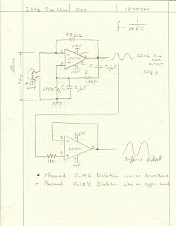
Jim's first iteration of the circuit consisted of a RC Wien Bridge, an LT1037 Opamp and a #327 Lamp. The Lamp is used as a variable resistor that starts out at a very low 98 Ohms DC resistance that helps get the Opamp oscillating (because of the increased gain) and ends up stabilizing at around 235 Ohms once it heats up (thus servo-ing the gain down to an equilibrium point that keeps the circuit oscillating).
I thought this would be a fun circuit to build up and recreate. Below is the ~1KHz Sine Wave Oscillator schematic; note I needed to add a LT1001 buffer, so I could measure the output waveform and hook it up to my Distortion Analyzer. Without the buffer the output's amplitude gets very jumpy.
I hooked everything up on the breadboard just to prove out the circuit then I transferred the circuit over to a more permanent FR4 copper PCB.
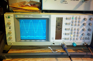
This circuit produces a nice looking Sine Wave that is about 12Vp-p.
The Lamp had roughly a 4Vp-p sinewave across it, so now I could calculate the approx. resistance of the Lamp when it is oscillating. The Lamp's Resistance during oscillation is 4V/((12V - 4V)/470) = 235 Ohms. With that measured information I was able to create an equivalent resistance model in LTSPICE that mimicked the lamps function in the circuit. (Here is a Link to my LTSPICE File)
All I did was make a switched resistance that started at approx. 98 Ohms (168 || 235) and then after 5ms the Lamps resistance changed to 235 Ohms.You can see from the simulation that after switching the resistance to 235 ohms the output wave form changes from a square wave to a sine wave.The real circuit servos to the larger 235 resistance value, so it isn't so abrupt.... but this equivalent circuit allows a rough approximation of what is going on.
I then hooked up the Oscillator up to my HP 331A Distortion Analyzer to see how good of Sine wave it was. I did this with another home brew oscillator in a previous blog.
I measured 0.18% Distortion. Not a bad Sine Wave (especially since my previous blog's circuit was 7.4% and most low-end Function Generators are appox. 1%), but it is way off from Jim's result of 0.0025%. I am not quite sure why Jim's results were so much better than mine. My HP 331A Distortion Analyzer hasn't been calibrated since 1987, so it could very well be off.... but the results are very repeatable with my Distortion Analyzer.
I did make an attempt at improving the distortion. Jim has an opamp rule "always invert (except when you can't)". What this means is opamp's like to have their non-inverting input at gnd; in our circuit the non-inverting input of the LT1037 isn't at a DC gnd. I hooked up a u741 opamp (U2) as shown in the schematic below to try and improve the distortion. This opamp servos to make the non-inverting input of the LT1037 at GND.
The distortion waveform did change, but it wasn't an improvement; I got roughly 0.4% distortion now. I'll have to play around with this circuit a bit more and see if I can figure out why my distortion is 0.18% and Jim's was 0.0025%.... a battle for another night.
Later that day......
It bugged me that my sine wave's distortion was still a lot higher than Jim's and I didn't want to blame it all on my uncalibrated Distortion Analyzer. I did some searching and came across a paper by Kenneth A. Kuhn "Sine Wave Oscillators" where he had built up this same circuit and plotted the Rf (feedback resistor) vs the output signal.
I was using a 470 Ohm feedback resistor and getting about 12Vp-p output signal. What happens if I change the feedback resistor to 320 Ohms and drop the output voltage to about 5Vp-p..... maybe 12Vp-p is a bit too high for the components I had.
I slapped in a 1K Ohm resistor in parallel with my 470 Ohm and got roughly 5Vp-p output. I then measured my distortion and was pleasantly surprised to see I had now reached 0.024%.... still and order of magnitude off from Jim's 0.0025% but now I think I maybe zeroing in on the limits of my uncalibrated equipment.
Now I think I have circuit I can base my DIY Function generator on. I just need some comparators to make a square wave output and an integrator to turn that into a triangle wave..... more fun to come!
References:
2) "Analog Circuit Design" - Jim Williams


I may be misremembering the book, but I thought the best performing circuit wound up replacing the lamp with a feedback controlled j-fet. Could that be the circuit he spec'd the low distortion figure for, not the lamp circuit?
ReplyDeleteYou are correct, Jim did later replace the lamp with a much more complex JFET circuit and got better distortion. I did want to try some of the other circuits, unfortunately I am at the noise floor of my Distortion Analyzer at 0.024% and wouldn't see any improvement if I tried.
ReplyDeleteDear sir,
ReplyDeleteThank you for this nice web page!
A quick question: what would happen if you leave out the lamp? Wouldn't it just do exactly the same?