Friday, April 6, 2012

Vichy DM4070 LCR Meter Teardown

A few weeks ago I was inspired by VK2ZAY's LC Test Oscillator video and wanted to build one of my own. So I jumped on ebay and bought a handful of J310 N-channel JFETs and started up LTSPICE to get a circuit sketched up.
The circuit simulated well and I jumped into prototyping.
Well long story short I couldn't get it working, so I started to suspect the inductors and caps I was using. The caps were el cheapo ebay bought parts and were shipped from Thailand, so I had little confidence they would hold up at 50MHz, also the inductors I was using weren't really suited for RF frequencies so I hand-wound my own aircore inductor. 

In the heat of debugging I decided I needed an LCR Meter to check out some of these components, so I went on to ebay and bought a Vichy DM4070 LCR Meter for $37.... I know this is an el cheapo ebay meter, but for home use it looked good. I have been pretty happy with it so far. It is not auto-ranging, but offers an adjustment pot to dial out any stray capacitance. It is well put together and looks sharp, which doesn't hurt :)

Upon tearing it open the first thing I noticed was the large amount of manual adjustment pots. Most of the higher priced LCR meters have a bit more of software calibration in them and don't have near as many pots as this one has.


There isn't a whole lot of protection circuitry; just some clamping diodes and a single varistor.... so don't be hooking up large voltages to this meter or smoke will come billowing out.


Not a lot to it, just a lot of passives, Analog Switches and Mux ICs. All the magic is under that epoxy blob, which is probably the Micro with internal ADC.

Now that I am armed with an LCR Meter hopefully I'll get that Oscillator up and running soon........

Saturday, January 28, 2012

Sword of Omens Hack

It is probably a good thing I have two little girls and no boys, because I have a little bit of an action figure toy fetish and I would go broke buying toys for me... I mean my boys if I had any. My downstairs office is covered with Starwars, Ironman, Thundercats, and Rambo action figures along with a vintage A-Team Mr. T. action figure I am pretty proud of :)

I just recently bought a Thundercats Deluxe Sword of Omens from ebay and even though it is pretty cool, one draw back is only the Thundercats logo side of the sword lights up; the Eye of Tundera side just hangs out and doesn't do anything. I just had to fix that......


I tore open the sword and found the 47 ohm series resistor and LED that light up the one side of the sword and I just tapped off that and soldered on another Red LED and 47 ohm resistor on the other side. I drilled a hole on the other side of the plastic and glued in the LED underneath the Eye of Thundera.
Now that both sides of the sword light up I can now save Third Earth from Ancient Spirits of Evil!!!

Arduino Battery Monitor Part II

In my last blog post I took an Adruino Uno and a Protoshield and made a simple battery monitor, so I could measure the voltage of a discharging 9V battery when it was drained through a constant 100mA load. Below is the 9V battery discharge curve:
The 100mA constant load was chosen because my ProtoStack Arduino Clone with LCD draws about 92mA and I wanted to write a sketch to display a battery bar and the approximate hours battery life left. Since all batteries have an internal equivalent series resistance (ESR), it is important to take that into account when only using a battery's voltage to monitor its state of charge. Since we discharged the battery through a load that is similar to the ProtoStack board with LCD, the ESR of the battery has automatically been accounted for in the voltage measurements.

With the plotted excel data from the discharge monitor I created a look-up table in software to approximate the battery life:

Battery Voltage               Hours Life Left                  Displayed Battery Bars
7.87V > Batt                        4.5hrs                                         4
7.45V > Batt <= 7.87V        4.0hrs                                         4
7.23V > Batt <= 7.45V        3.5hrs                                         4
7.08V > Batt <= 7.23V        3.0hrs                                         3
6.94V > Batt <= 7.08V        2.5hrs                                         3
6.77V > Batt <= 6.94V        2.0hrs                                         2
6.56V > Batt <= 6.77V        1.5hrs                                         2
6.30V > Batt <= 6.56V        1.0hrs                                         1
5.71V > Batt <= 6.30V        0.5hrs                                         1
              Batt <= 5.71V        mins left                                     0

Here is the sketch I wrote: link

I tied the input voltage through a resistor divider (220K Ohm series and 100K Ohm shunt) to the A0 pin on the micro.
One issue I ran into was the 9V battery can go down as low as 5.71V before it is completely dead. The ProtoStack board has a 1N4004 reverse polarity protection diode and a 7805 Linear Regulator to generate its 5V rail. These components require that the input voltage be greater than 7.8V in order to create the 5V rail properly.
So I replaced the 1N4004 diode with a schottky diode that has a much lower 0.2V forward voltage and used a L4941 5V linear regulator to replace the 7805. The L4941 has a drop out voltage of less than 0.45V when sourcing 1Amp. With these mods I was able to go down to 5.30V input voltage before the LCD stopped functioning.
I used the Parallax 16x2 LCD commands to create the custom characters for the "EH" and Full & Empty Battery Bar Segments. Here is a link to the spreadsheet I used to calculate the values for the custom characters.

This was a fun project to get myself familiar with the Arduino Analog pins. Now my ProtoStack Board is all ready for a future portable battery powered electronics project.

Monday, January 9, 2012

Arduino Based Battery Discharge Monitor

Trying to figure out the capacity left in a battery based on only its voltage is difficult. The equivalent-series-resistance (ESR) of the battery makes the cell's voltage a function of the current that is being drawn from it. For this reason I like to measure and plot the discharge of a battery, I am using, with a load current that matches my circuit. With this data I can estimate the capacity left in the battery at a given voltage.

I setup an Arduino Uno to measure a 9V battery's voltage along with a sense voltage to monitor the current leaving the battery through a 10 Ohm sense resistor.
I used the current sink from a previous project and set it to 100mA. I chose 100mA, because my Protostack Arduino Clone with LCD draws roughly 92mA from its DC input and the goal is to have this board estimate the battery capacity left based the 9V battery's measured voltage.
I modified my Adruino Protoshield to have two 220K Ohm (series) and 100K Ohm (shunt) voltage dividers put in front of the Analog Inputs AN0 and AN1. This will protect these pins from voltages higher than 5V and up to 15VDC. This protoshield also still has on the DS1307 RTC and CR2032 battery backup from my Arduino RTC project. This RTC will come in handy and allow me to reference my measured voltages to a given time on the DS1307.
 A little bit of hot glue acts as a strain-relief on the AN0, AN1 and GND wires.

The software is pretty straight forward. I grab the ADC counts read by AN0 & AN1 and then convert the counts to a voltage. I then have to scale the voltage based on the 220K & 100K Ohm resistor divider. After that I grab the Date and Time from the DS1307 RTC and print everything out the comport at 9600 baud. Then I wait a fixed length of time (1 second) and repeat everything,

My full sketch can be found here.

Below is my main loop routine:

void loop()
{
  // read the analog in value:
  BatteryValue  = analogRead(BatteryPin);
  SenseValue     = analogRead(SensePin);

  // convert the 0-1023 ADC value to a voltage (Note: 5V reference)
  BatteryValue  = BatteryValue/1023 * 5;
  SenseValue    = SenseValue/1023 * 5;
 
  // Compensate the Voltage for the external Resistor divider
  // (220K series, 100K shunt) in front of the AN0-1 pins
  BatteryValue  = BatteryValue / 0.315;
  SenseValue    = SenseValue / 0.315;
 
  CurrentValue = (BatteryValue - SenseValue) / SenseResistor;

  getDateDs1307(&second, &minute, &hour, &dayOfWeek, &dayOfMonth, &month, &year);    

  // print the results to the serial monitor:
  Serial.print("\n" );
  Serial.print(hour, DEC);
  Serial.print(":");
  Serial.print(minute, DEC);
  Serial.print("\t\t" );                      
  Serial.print(BatteryValue);     
  Serial.print("\t\t");     
  Serial.print(SenseValue);
  Serial.print("\t\t");     
  Serial.print(CurrentValue);   

  delay(60000);   // 1 min Delay
}


The sketch outputs all the data in a nice table format out the comport and into Hyper Terminal or your other favorite Terminal application:
This data can then be cut & pasted into Excel and plotted:
The 9V battery lasted a little better than 4.5 hours at 100mA discharge before it gave up. You can see that a constant 1V difference between the Battery Voltage and the Sense Voltage is shown. This confirms that a constant 100mA was pulled through the 10 Ohm sense resistor via the current sink

To be continued...... Next I'll be writing a sketch to display hours left on the 9V battery powering my ProtoStack Arduino Clone.

Part II here: http://embeddederic.blogspot.com/2012/01/arduino-battery-monitor-part-ii.html

Wednesday, January 4, 2012

HP 331A Distortion Analyzer Teardown

While messing with my RC Wien Bridge Oscillator I noticed I was getting some erratic readings now and then,  so I decided to do a bit of a teardown on my HP 331A Distortion analyzer. I did notice that some of the boards were connected with pins and sockets and they were pretty loose. Grabbing the soldering iron I hard soldered the wires to the boards in hopes my erratic behavior would go away.

Once I put the Distortion Analyzer back together I remeasured my RC Wien Bridge Oscillator Distortion and was getting a very repeatable 0.025-0.030%. I am still off from Jim's 0.0025%, but I think I am really pushing the resolution on this old piece of equipment that was last serviced in 1965 and last calibrated in 1987.


Below are picks from the HP 331A tear down:


Monday, January 2, 2012

Sine Waving into the New Year!

I have been slowly reading through Jim Williams "Analog Circuit Design" book. Not slowly because it is boring, it is actually very interesting and a good read; I just get easily distracted and it has been a few weeks since I picked it up. I am about 200 pages or so into it and my favorite chapter so far has been the one where Jim Williams describes the steps he took while recreating William Hewlett's Model 200A Wien Bridge Oscillator. It is essentially the same project described in Linear Tech's AN43 Appnote, but with a lot more background and Jim describes the inner workings very conversationally in the book.

Jim's first iteration of the circuit consisted of a RC Wien Bridge, an LT1037 Opamp and a #327 Lamp. The Lamp is used as a variable resistor that starts out at a very low 98 Ohms DC resistance that helps get the Opamp oscillating (because of the increased gain) and ends up stabilizing at around 235 Ohms once it heats up (thus servo-ing the gain down to an equilibrium point that keeps the circuit oscillating).

I thought this would be a fun circuit to build up and recreate. Below is the ~1KHz Sine Wave Oscillator schematic; note I needed to add a LT1001 buffer, so I could measure the output waveform and hook it up to my Distortion Analyzer. Without the buffer the output's amplitude gets very jumpy.

I hooked everything up on the breadboard just to prove out the circuit then I transferred the circuit over to a more permanent FR4 copper PCB.
This circuit produces a nice looking Sine Wave that is about 12Vp-p.
The Lamp had roughly a 4Vp-p sinewave across it, so now I could calculate the approx. resistance of the Lamp when it is oscillating. The Lamp's Resistance during oscillation is 4V/((12V - 4V)/470) = 235 Ohms. With that measured information I was able to create an equivalent resistance model in LTSPICE that mimicked the lamps function in the circuit. (Here is a Link to my LTSPICE File)
All I did was make a switched resistance that started at approx. 98 Ohms (168 || 235) and then after 5ms the Lamps resistance changed to 235 Ohms.You can see from the simulation that after switching the resistance to 235 ohms the output wave form changes from a square wave to a sine wave.The real circuit servos to the larger 235 resistance value, so it isn't so abrupt.... but this equivalent circuit allows a rough approximation of what is going on.

I then hooked up the Oscillator up to my HP 331A Distortion Analyzer to see how good of Sine wave it was. I did this with another home brew oscillator in a previous blog.

I measured 0.18% Distortion. Not a bad Sine Wave (especially since my previous blog's circuit was 7.4% and most low-end Function Generators are appox. 1%), but it is way off from Jim's result of 0.0025%. I am not quite sure why Jim's results were so much better than mine. My HP 331A Distortion Analyzer hasn't been calibrated since 1987, so it could very well be off.... but the results are very repeatable with my Distortion Analyzer.

I did make an attempt at improving the distortion. Jim has an opamp rule "always invert (except when you can't)". What this means is opamp's like to have their non-inverting input at gnd; in our circuit the non-inverting input of the LT1037 isn't at a DC gnd. I hooked up a u741 opamp (U2) as shown in the schematic below to try and improve the distortion. This opamp servos to make the non-inverting input of the LT1037 at GND.
The distortion waveform did change, but it wasn't an improvement; I got roughly 0.4% distortion now. I'll have to play around with this circuit a bit more and  see if I can figure out why my distortion is 0.18% and Jim's was 0.0025%.... a battle for another night.

Later that day......
It bugged me that my sine wave's distortion was still a lot higher than Jim's and I didn't want to blame it all on my uncalibrated Distortion Analyzer. I did some searching and came across a paper by Kenneth A. Kuhn "Sine Wave Oscillators" where he had built up this same circuit and plotted the Rf (feedback resistor) vs the output signal.
I was using a 470 Ohm feedback resistor and getting about 12Vp-p output signal.  What happens if I change the feedback resistor to 320 Ohms and drop the output voltage to about 5Vp-p..... maybe 12Vp-p is a bit too high for the components I had.

I slapped in a 1K Ohm resistor in parallel with my 470 Ohm and got roughly 5Vp-p output. I then measured my distortion and was pleasantly surprised to see I had now reached 0.024%.... still and order of magnitude off from Jim's 0.0025% but now I think I maybe zeroing in on the limits of my uncalibrated equipment.

Now I think I have  circuit I can base my DIY Function generator on. I just need some comparators to make a square wave output and an integrator to turn that into a triangle wave..... more fun to come!

References:
2) "Analog Circuit Design" - Jim Williams

Sunday, December 25, 2011

Merry Christmas 80's style!

I loved Kings Quest & Space Quest as a kid. Great old school games!

You can download updated versions of these old school games here.

Saturday, December 17, 2011

Rudolph the Red (555 Timer based LED) Nosed Reindeer

It is Sat. afternoon, mom is in Kentucky visiting family and I have the girls....... what should we do? A 555 timer based Rudolph the Red-Nosed Reindeer of course!

I grabbed some scrap double sided PCB material and cut out a cookie cutter like reindeer shape. Then I had my 4-year old daughter sand the edges and buff the surface with some steel wool.

We then soldered the 1Hz Astable 555-Timer circuit dead bug style (with a lot of Daddy supervision). My girls were pretty pumped to see the nose blink when we turned on the power supply for the first time.
I then soldered on a 9V battery clip, so the battery acts as the stand.


We had a fun afternoon without mommy.... maybe my nerdyness will rub off on them and I'll have two very pretty engineer daughters!

ITead Studio Surprise Xmas Gift

A couple weeks ago I got an email from ITead Studio saying since I signed up to follow them on Twitter they were going to send me a free Mystery Xmas gift.... pretty cool huh!

Just this past week I received a small envelope from ITead Studio. Inside was a coupon for 5% off my next order, a business card, 5 prototyping jumper wires, and a PCB showing ITead's capabilities.

I thought this was a pretty cool way to advertise. I think I'll have to give them a try with my next project pcb. Thanks ITead for the gift!

Happy Holidays - XY Scope Fun!

Last week I saw a neat post from Johngineer where he took an Arduino and a couple RC filters and made a Xmas Tree on his scope.
I thought this would be a fun project to replicate with my 2 and 4 year old daughters, but I wanted to make a small tweak and display a picture of Frosty the Snowman. My two year old discovered the old Frosty the Snowman cartoons this year and is constantly asking to "watch a frosty".

I downloaded John's Arduino sketch and took a look at it to see what I'd have to do to change the picture displayed on the scope. His code is very well laid out and the picture is defined by the number of points and the X Y coordinates stored as two arrays.

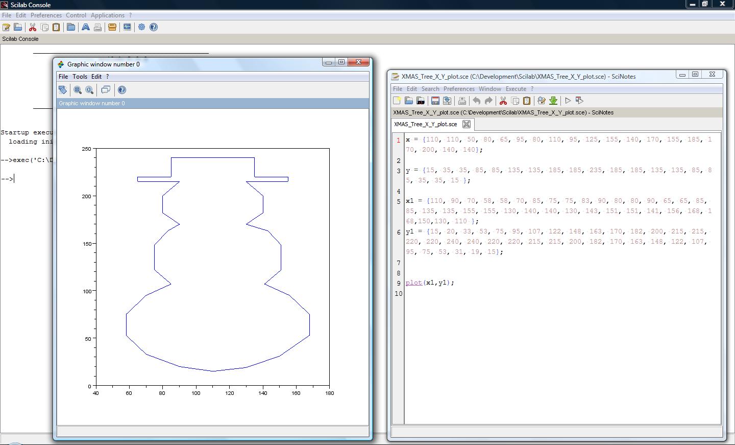
Now how do I draw a picture of a snowman and get X Y coordinates out of it? I tried GIMP and Paint, but ended up using Scilab...... yes a fancy math program to draw a snowman! The nice thing about Scilab is you can plot pictures using the same X & Y arrays needed for the Arduino sketch.

I could have gotten all fancy and used sin & cos equations to get a nice smooth circle, but a line segment circle gets the job done too, and is equally impressive to a two year old :)

Once I got the X Y coordinates figured out I cut and paste them in to John's sketch and loaded it into my ProtoStack Arduino Clone from a previous post.
Here is John's sketch with my added X1 & Y1 coordinates for the snowman pic. link


We grabbed a bread board and I let my 4 year old insert the 10K Ohm and 0.1uF caps and hook up the scope probes.
With a few tweaks to the scope's settings we got a nice picture of Frosty the Snowman.

My daughters had fun making him taller and shorter and skinny and fat all with a few button presses. Thanks John for the great idea; my girls and I had a lot of fun!