Monday, January 2, 2012

Sine Waving into the New Year!

I have been slowly reading through Jim Williams "Analog Circuit Design" book. Not slowly because it is boring, it is actually very interesting and a good read; I just get easily distracted and it has been a few weeks since I picked it up. I am about 200 pages or so into it and my favorite chapter so far has been the one where Jim Williams describes the steps he took while recreating William Hewlett's Model 200A Wien Bridge Oscillator. It is essentially the same project described in Linear Tech's AN43 Appnote, but with a lot more background and Jim describes the inner workings very conversationally in the book.

Jim's first iteration of the circuit consisted of a RC Wien Bridge, an LT1037 Opamp and a #327 Lamp. The Lamp is used as a variable resistor that starts out at a very low 98 Ohms DC resistance that helps get the Opamp oscillating (because of the increased gain) and ends up stabilizing at around 235 Ohms once it heats up (thus servo-ing the gain down to an equilibrium point that keeps the circuit oscillating).

I thought this would be a fun circuit to build up and recreate. Below is the ~1KHz Sine Wave Oscillator schematic; note I needed to add a LT1001 buffer, so I could measure the output waveform and hook it up to my Distortion Analyzer. Without the buffer the output's amplitude gets very jumpy.

I hooked everything up on the breadboard just to prove out the circuit then I transferred the circuit over to a more permanent FR4 copper PCB.
This circuit produces a nice looking Sine Wave that is about 12Vp-p.
The Lamp had roughly a 4Vp-p sinewave across it, so now I could calculate the approx. resistance of the Lamp when it is oscillating. The Lamp's Resistance during oscillation is 4V/((12V - 4V)/470) = 235 Ohms. With that measured information I was able to create an equivalent resistance model in LTSPICE that mimicked the lamps function in the circuit. (Here is a Link to my LTSPICE File)
All I did was make a switched resistance that started at approx. 98 Ohms (168 || 235) and then after 5ms the Lamps resistance changed to 235 Ohms.You can see from the simulation that after switching the resistance to 235 ohms the output wave form changes from a square wave to a sine wave.The real circuit servos to the larger 235 resistance value, so it isn't so abrupt.... but this equivalent circuit allows a rough approximation of what is going on.

I then hooked up the Oscillator up to my HP 331A Distortion Analyzer to see how good of Sine wave it was. I did this with another home brew oscillator in a previous blog.

I measured 0.18% Distortion. Not a bad Sine Wave (especially since my previous blog's circuit was 7.4% and most low-end Function Generators are appox. 1%), but it is way off from Jim's result of 0.0025%. I am not quite sure why Jim's results were so much better than mine. My HP 331A Distortion Analyzer hasn't been calibrated since 1987, so it could very well be off.... but the results are very repeatable with my Distortion Analyzer.

I did make an attempt at improving the distortion. Jim has an opamp rule "always invert (except when you can't)". What this means is opamp's like to have their non-inverting input at gnd; in our circuit the non-inverting input of the LT1037 isn't at a DC gnd. I hooked up a u741 opamp (U2) as shown in the schematic below to try and improve the distortion. This opamp servos to make the non-inverting input of the LT1037 at GND.
The distortion waveform did change, but it wasn't an improvement; I got roughly 0.4% distortion now. I'll have to play around with this circuit a bit more and  see if I can figure out why my distortion is 0.18% and Jim's was 0.0025%.... a battle for another night.

Later that day......
It bugged me that my sine wave's distortion was still a lot higher than Jim's and I didn't want to blame it all on my uncalibrated Distortion Analyzer. I did some searching and came across a paper by Kenneth A. Kuhn "Sine Wave Oscillators" where he had built up this same circuit and plotted the Rf (feedback resistor) vs the output signal.
I was using a 470 Ohm feedback resistor and getting about 12Vp-p output signal.  What happens if I change the feedback resistor to 320 Ohms and drop the output voltage to about 5Vp-p..... maybe 12Vp-p is a bit too high for the components I had.

I slapped in a 1K Ohm resistor in parallel with my 470 Ohm and got roughly 5Vp-p output. I then measured my distortion and was pleasantly surprised to see I had now reached 0.024%.... still and order of magnitude off from Jim's 0.0025% but now I think I maybe zeroing in on the limits of my uncalibrated equipment.

Now I think I have  circuit I can base my DIY Function generator on. I just need some comparators to make a square wave output and an integrator to turn that into a triangle wave..... more fun to come!

References:
2) "Analog Circuit Design" - Jim Williams

Sunday, December 25, 2011

Merry Christmas 80's style!

I loved Kings Quest & Space Quest as a kid. Great old school games!

You can download updated versions of these old school games here.

Saturday, December 17, 2011

Rudolph the Red (555 Timer based LED) Nosed Reindeer

It is Sat. afternoon, mom is in Kentucky visiting family and I have the girls....... what should we do? A 555 timer based Rudolph the Red-Nosed Reindeer of course!

I grabbed some scrap double sided PCB material and cut out a cookie cutter like reindeer shape. Then I had my 4-year old daughter sand the edges and buff the surface with some steel wool.

We then soldered the 1Hz Astable 555-Timer circuit dead bug style (with a lot of Daddy supervision). My girls were pretty pumped to see the nose blink when we turned on the power supply for the first time.
I then soldered on a 9V battery clip, so the battery acts as the stand.


We had a fun afternoon without mommy.... maybe my nerdyness will rub off on them and I'll have two very pretty engineer daughters!

ITead Studio Surprise Xmas Gift

A couple weeks ago I got an email from ITead Studio saying since I signed up to follow them on Twitter they were going to send me a free Mystery Xmas gift.... pretty cool huh!

Just this past week I received a small envelope from ITead Studio. Inside was a coupon for 5% off my next order, a business card, 5 prototyping jumper wires, and a PCB showing ITead's capabilities.

I thought this was a pretty cool way to advertise. I think I'll have to give them a try with my next project pcb. Thanks ITead for the gift!

Happy Holidays - XY Scope Fun!

Last week I saw a neat post from Johngineer where he took an Arduino and a couple RC filters and made a Xmas Tree on his scope.
I thought this would be a fun project to replicate with my 2 and 4 year old daughters, but I wanted to make a small tweak and display a picture of Frosty the Snowman. My two year old discovered the old Frosty the Snowman cartoons this year and is constantly asking to "watch a frosty".

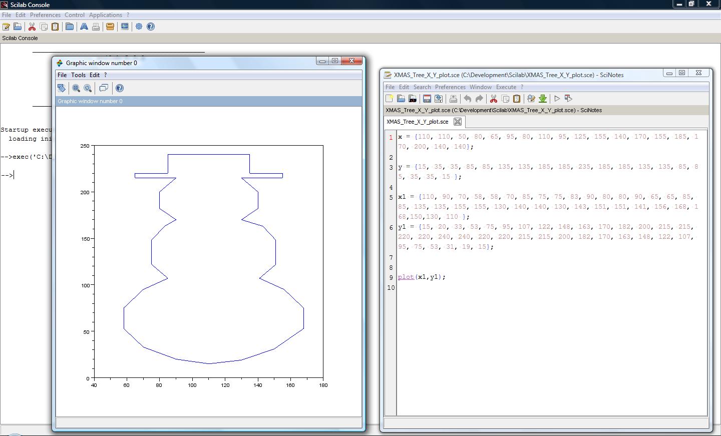
I downloaded John's Arduino sketch and took a look at it to see what I'd have to do to change the picture displayed on the scope. His code is very well laid out and the picture is defined by the number of points and the X Y coordinates stored as two arrays.

Now how do I draw a picture of a snowman and get X Y coordinates out of it? I tried GIMP and Paint, but ended up using Scilab...... yes a fancy math program to draw a snowman! The nice thing about Scilab is you can plot pictures using the same X & Y arrays needed for the Arduino sketch.

I could have gotten all fancy and used sin & cos equations to get a nice smooth circle, but a line segment circle gets the job done too, and is equally impressive to a two year old :)

Once I got the X Y coordinates figured out I cut and paste them in to John's sketch and loaded it into my ProtoStack Arduino Clone from a previous post.
Here is John's sketch with my added X1 & Y1 coordinates for the snowman pic. link


We grabbed a bread board and I let my 4 year old insert the 10K Ohm and 0.1uF caps and hook up the scope probes.
With a few tweaks to the scope's settings we got a nice picture of Frosty the Snowman.

My daughters had fun making him taller and shorter and skinny and fat all with a few button presses. Thanks John for the great idea; my girls and I had a lot of fun!

Wednesday, November 30, 2011

Happy (belated) Thanksgiving!

Thanksgiving was just last weekend and it is a neat USA holiday where we get together as a family, eat way too much and reflect on what we are thankful for. I am thankful for many things: family, friends, health.... the usual stuff, but I am also thankful for my Blogs readers. I started this Blog over a year ago and since June it has just taken off.

In June I was pumped to have a couple hundred hits on my blog a month.... I mean how many people want to read about some guy in Minnesota, USA Rant about his Electronics endeavors. I was surprised that over just a few months time it has grown to over 2,000 hits a month and keeps growing. This is a huge incentive and mental push to get me off my butt and working on fun side projects in my home lab. This is also a huge testimony to the true power of the Internet connecting people all over the world. I love and appreciate all the connections and contacts I have made all over the world through this blog.


Thank you all for your support! I have many cool project ideas for the coming year and thanks to you all I have the drive to get them moving!

Happy (belated) Thanksgiving!

Saturday, November 26, 2011

ProtoStack ATmega328 Kit Review (Arduino Clone Build)

Back in October I managed to get my 7400 Logic PLL Based Switcher in the third place category of the Dangerous Prototypes Open 7400/4000 Series Logic Contest. Dangerous Prototypes had the neat idea to let the winners pick their own prizes from the many sponsor donated kits & parts; that way everyone gets something they want. I picked out one of the 3x ProtoStack ATmega328 Developments Kits they donated. I've been messing around with my Arduino Uno for a while and was looking to expand my Atmel AVR knowledge a bit and thought building up this kit and turning it into an Arduino clone would be a fun project. I figured I'd give a little review of the kit as I went along as well.

The ProtoStack ATmega328 Development Kit came in a well packaged antistatic bag that had individual heat sealed sections for the PCB and components. I also got a free USBasp programmer which I was not expecting (Thanks ProtoStack!). I did have an Atmel JTAG ICE mk-II that I was planning on using to program the ATmegga328, but the USBasp is a bit more compact and I thought I'd use that instead.
The ProtoStack User's Guide for the ATmega328 kit is very well laid out and is easy to follow. They have put a lot of effort documenting different build configurations to easily change how the board is powered or programmed. They clearly document how to power the board with a DC Jack, USB Device, Coincell CR2032 Battery, or Terminal Block. They also show how to add board stacking connectors.
It took less than 30mins to solder up the kit. I did make a few small tweaks to my build. The kit comes with a 20MHz Xtal, but I wanted my board to be Arduino sketch compatible so I installed a 16MHz Xtal instead. I also added a ST Micro ST232CN RS232 level converter (connected to D0 [Rx] and D1 [Tx] and a DB-9 female connector. This RS232 connection allows me to use a USB-to-RS232 dongle to connect this kit to my computer and download sketches from the Arduino IDE. I love that the standard Arduino's come with the USB Device interface built in, but having a native RS232 interface on this kit helps me connect to all my legacy peripherals that still use RS232. I also connected up a Parallax 16x2 Serial LCD by hooking up the RX pin of the LCD display to the D1 [Tx] pin of the micro and hooking up 5V and GND of the display to the boards power rails.
For kicks I added one of Adafruit's cool ATmega 168/328 labels on the micro, so I don't have to grab the schematic or datasheet when doing a quick measurement or mod.
Overall I was extremely happy with how quickly the ProtoStack ATmega328 kit went together; my one complaint is that ProtoStack provides very little programming tutorial help other than pointing to several third party USBasp compatible websites/software. The struggle I had was all of these websites assumed the user had a basic understanding of programming Atmel AVR's which I didn't. All I had done before is used the Arduino IDE to program parts that already had the Arduino bootloader installed.... so that was my first step, I needed to use the USBasp to program in the Arduino bootloader then I should be able to use the RS232 interface to load sketches onto this board.

The first thing I did was download Atmel's AVR Studio for Windows. I got that installed and was surprised to find that even though the USBasp programmer had a windows driver it was not compatible with AVR Studio.... fail. So I grabbed my mk-II programmer I had gotten from a friend and was surprised to find that I could not get that to work either..... double fail. It turned out that the mk-II programmers USB Device interface was broken and it worked fine if I used its RS232 connection instead. This worked, but I wanted to get the USBasp programmer working, so I downloaded a few other free Windows AVR programs.

I downloaded  WinAVR which is compatible with the USBasp, but it kept crashing and locking up on my Vista laptop. So I downloaded eXtremeBurner-AVR which ran fine, but it didn't have the ATmega328 in it's list of parts it was compatible with. At this point I gave up on finding a Windows compatible AVR program that worked with the USBasp and rebooted my laptop and started up my Ubuntu 11.04 Linux distribution.

I loaded AVRdude and started searching for tutorials on how to load the Arduino bootloader into blank parts with AVRdude. This wasn't too hard to find; Adafruit's LadyAda and Sparkfun all had well written tutorials to walk me through the process.

First thing I did was look in my Arduino IDE directory for the \arduino-0022\hardware\arduino\boards.txt file. This text file told me that for an Arduino Uno with an ATmega328 I needed to use the \arduino-0022\hardware\arduino\bootloaders\optiboot\optiboot_atmega328.hex bootloader file with the low fuses set to 0xFF, high fuses set to 0xDE, extended fuses set to 0x05, and the lock bits set to 0x0F. Cool, now I had all the info I needed to program the Arduino bootload into my board.

Next I needed to figure out how to use the USBasp with AVRdude. After plugging the USBasp into my laptops USB port I struggled a bit to get AVRdude to recognize that the USBasp was plugged in.

avrdude: error: could not find USB device "USBasp" with vid=0x16c0 pid=0x5dc 

After Google searching for clues as to why I couldn't get it to work I found many posts stating that the Linux permissions for the USBasp required AVRdude be run by the super-user (su) or root. I tried that and still wasn't having any luck. Using the lsusb command I could see that the USBasp programmer was being recognized but it looked like there was a PID & VID ID conflict error with libusb.

ID 16c0:05dc VOTI shared ID for use with libusb 

After trying to read the AVR forums for several hours to try and find a solution I remembered that some of my USB flash drives wouldn't work with Ubuntu when plugged directly into my laptop's USB ports, but worked fine when plugged into a 4-1 USB hub that was plugged into my laptop. So I tried plugging the USBasp into my 4-1 USB hub and once I got the permissions setup right it worked great!!!!! (Yeah now I was cooking!)

I loaded up the command shell and moved to the folder that had the optiboot_atmega328.hex file in it and typed in the following command into AVRdude:

avrdude -b 19200 -c usbasp -p m328p -F -v -e -U flash:w:optiboot_atmega328.hex -U efuse:w:0x05:m -U hfuse:w:0xD6:m -U lfuse:w:0xFF:m -U lock:w:0x0F:m

  • "avrdude" runs the program
  • "-b 19200" is the baud rate avrdude sends the data to the programmer
  • "-p m328p -F" sets the device to ATmega328p... the -F kills the warning i kept getting because I had a ATmega328 - no "F", but AVRdude doesn't have a non-F part in it's list of supported devices.
  • "-v -e" erase and verify the Flash of the part
  • "-U flash:w:optiboot_atmega328.hex" is the file we want to load into the device
  • "-U efuse:w:0x05:m -U hfuse:w:0xD6:m -U lfuse:w:0xFF:m -U lock:w:0x0F:m" sets all the fuse and lock bits. These bits configure the devices boot, xtal and configuration settings
Below is the output of AVRdude as the part is being programmed.

 A complete text file of the output is available here for download.

Now that I had the Arduino Uno bootloader loaded into the micro I loaded up the Arduino IDE and wrote a small sketch to display a message on the Parallax Serial LCD.
The one quirk with this Arduino clone implementation is I have to press and release the reset button at just the right time when downloading a sketch. As soon as the "Binary sketchsize......" message shows up I quickly press and release the reset button and 8 out of 10 times I can successfully download the sketch into my board. It is a timing thing, the Ardunio IDE only waits so long to receive confirmation from the bootloader running on the micro before it errors out on the IDE. If it fails to download it is no big deal I just try again and press and release the reset button. I have gotten pretty good and timing it just right.


Overall I am pretty happy with the ProtoStack ATmega328 Development Kit and would highly recommend anyone getting one. I am excited to build up a few new projects with this board; having the extra prototyping space without having to stack a proto shield is a huge plus. Thanks ProtoStack for sponsoring the 7400 contest and getting me this kit and USBasp programmer!
Also Thank You Dangerous Prototypes for putting on the contest! It was a lot of fun seeing all the cool project ideas.

Monday, November 21, 2011

An Analog Life - Remembering Jim Williams

I recently came across this video from the Computer History Museum describing Jim Williams - An Analog Life exhibit. YouTube Video Link


The video is a bit long (1hr 18mins), but worth watching. I clipped out 4 mins of the video and have that below. This is part of the actual video playing at the exhibit.


I also just got copies of two books Jim wrote. I am looking forward to reading these on my 30 hour+ plane ride to China and back in Dec.


My review of these books to come......

Friday, November 18, 2011

Altoids Fume Extractor

Lately I've been soldering quite a bit at home and thought a fan based fume extractor would be a good investment. I came across this MAKE video recently that describes how to build one that fits in an Altoids box.

I dug around in my junk box and found a 24VDC fan. This fan was a bit too deep to fit in a single Altoids box and still have room for a carbon filter, so I had the idea to solder two Altoids boxes together. One would house a 9V battery, the Switch and the Fan. The other box would house 1/2 a Pet Co. Aquarium Carbon Filter and one more 9V battery.

Below is what I came up with:


The two 9V batteries in series get me 18V which is a bit low for the 24V fan, but it still works well and uses parts I just had lying around. The two boxes soldered together solution worked out well because it stands up better and won't tip over as easily as the single Altoids box version would.

Now I can solder away all day and not get a sore throat from all the flux fumes!

Wednesday, November 2, 2011

Open 7400 Logic Contest Winners!

The winners of Dangerous Prototypes Open 7400/4000 Logic Series Design Contest were announced today. Check out the Link.

Congrats to all the winners! My project even managed a spot in the Third place group, very cool!

Thanks Dangerous Prototypes & Sponsors and thanks to all the Judges!